R and D phase This product is in active research and development. It is not yet available for sale, figures are design targets and images are engineering renders.
In development

Modular Low-Voltage Power Platform

Your equipment
never sees the
outage.

A 12 V-native DC power and backup platform for routers, cameras, gateways and single-board computers. Battery and mains share one low-voltage path, so when the power drops your devices keep running instead of rebooting.

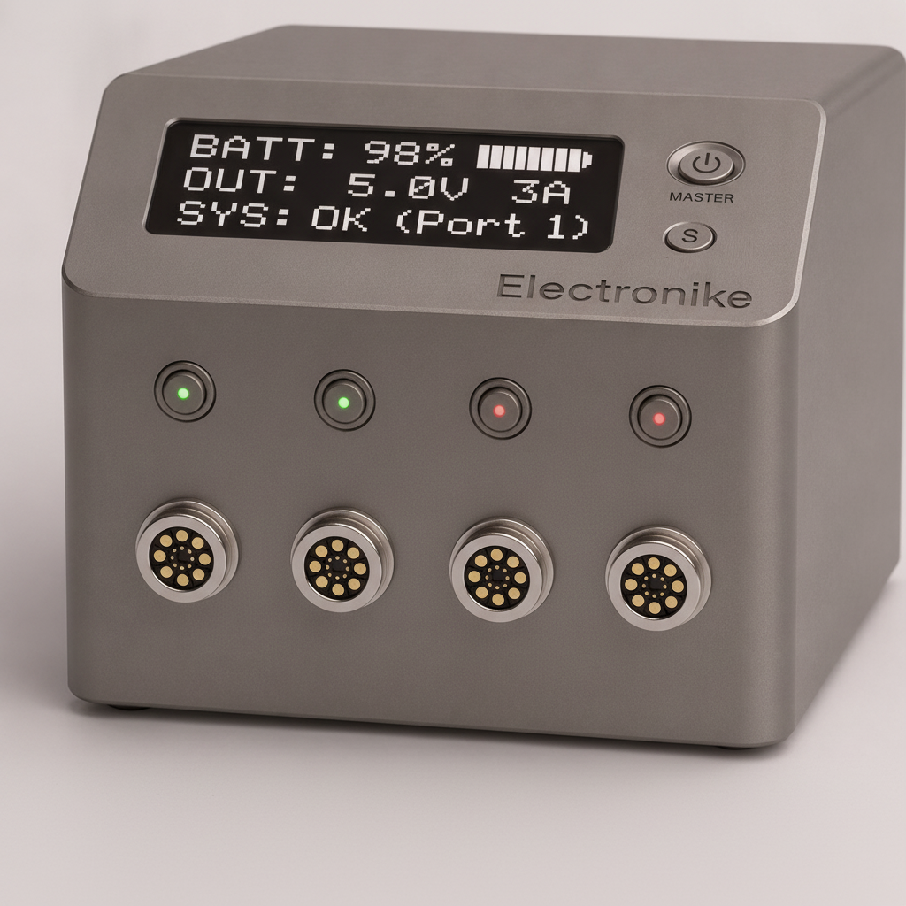
Electronike base unit with status display, master switch and four magnetic expansion ports NO-BREAK TRANSFER 153 Wh LiFePO4 4 PORTS · 16 OUTPUTS
153Wh
LiFePO4 energy on board
62W
Managed system power
16
Individually managed outputs
4
Magnetic expansion ports
100x
Interruptions tested at 10 A

Why it is not another mini UPS

Eight things a conventional
UPS cannot do.

A standard UPS lifts battery DC up to mains AC so your adapter can drop it straight back down again. We removed that round trip and put intelligence on every single output.

01

True no-break DC power

Ideal-diode ORing between external supply and battery. No firmware sits in the transfer path, so connected devices never lose their rail.

02

12 V-native architecture

Battery and internal distribution stay in low-voltage DC. No internal inverter, no DC to AC to DC detour.

03

16 managed outputs

One system replaces a UPS, a power strip and a drawer full of mismatched wall adapters.

04

Modular expansion

Different output modules connect to the same base platform over a CAN-FD bus, hot-pluggable and authenticated.

05

Per-device metering

Voltage, current and power measured on every port. Each device can be monitored, protected and restarted on its own.

06

Priority load shedding

You rank your devices. Non-essential loads drop first so the critical ones stay up far longer during an outage.

07

Owner-replaceable battery

Approved protected 12 V LiFePO4 packs from 7 to 12 Ah in a standard case size. The product outlives its battery.

08

Local and cloud control

Wi-Fi, Bluetooth LE and cloud together. Bluetooth keeps working during the exact event a UPS exists for.

The power path

Transfer that hardware
handles, not software.

Mains supply and battery meet at an ideal-diode ORing stage. Whichever source is higher feeds the bus, and the handover happens in the analogue domain. There is no detection delay, no relay click and no firmware decision to wait for.

Above it sits the managed layer, an eFuse holding the system inside a 4.98 A envelope, then four magnetic ports feeding intelligent modules over CAN-FD.

3
Fabricated boards measured
10 A
Full design current under test
100x
Repeated power interruptions
External supply 12 V DC input LiFePO4 pack 12.8 V / 12 Ah 153 Wh, replaceable Ideal-diode ORing no firmware in the path Main eFuse 4.98 A / 62 W charge ceiling 13.27 V 12 V managed bus metered, budgeted, shed by priority Port 1 USB-C 5 V Port 2 DC 3-12 V Port 3 module Port 4 module CAN-FD + power

Expansion modules

Four magnetic ports.
You choose what plugs in.

Every module carries its own microcontroller, protection, metering and CAN-FD identity. Connect one and the base unit authenticates it cryptographically before a single watt is released.

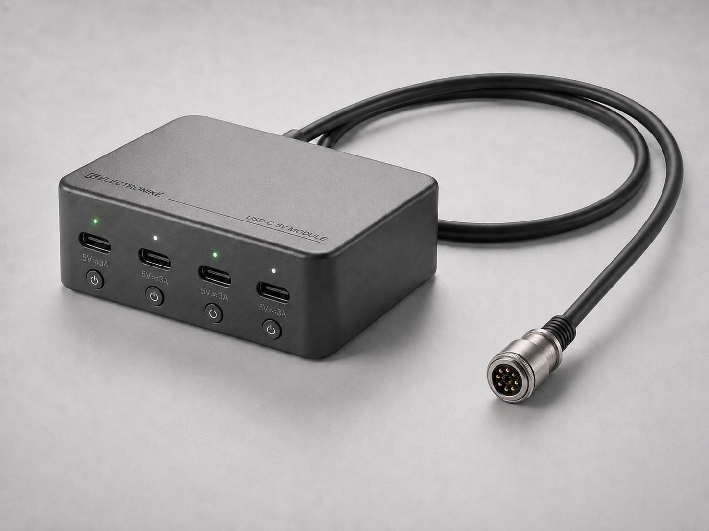
USB-C 5 V expansion module with four ports, per-port buttons and a magnetic connector cable

USB-C 5 V module

Four individually controlled and metered USB-C outputs, fixed at 5 V and up to 3 A. No USB PD negotiation, which means no chance of a device seeing a voltage it should never get.

5 V fixed3 A per port 4 outputsPer-port meteringRemote reboot
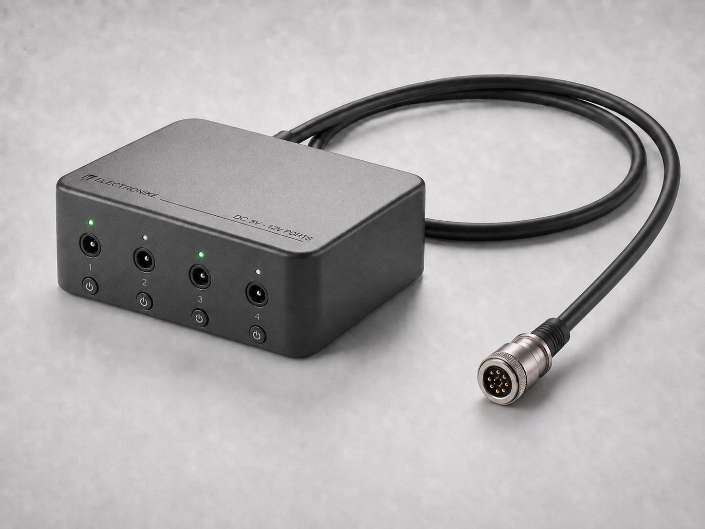
Variable-voltage DC expansion module with four barrel-jack outputs and a magnetic connector cable

Variable-voltage DC module

Four barrel-jack outputs, each configurable to 3, 5, 6, 9 or 12 V. One module retires a shelf of different wall adapters, and adjustable voltage is deliberately restricted to this connector type.

3 / 5 / 6 / 9 / 12 V4 outputs Per-port current limitHot-pluggable

Blind-mate interface

A connector built for the field, not the bench.

16 pin
Power contacts plus dedicated signal contacts
IP65
Dust and water protected structure
10,000
Rated mating cycles minimum
2.0 kgf
Magnetic hold, breaks away on a pull

Full capability set

Everything the platform does.

Software and connectivity

The app still works
when the internet does not.

Cloud, local Wi-Fi and direct Bluetooth LE run side by side. When a site loses mains power and the router goes with it, Bluetooth keeps you in contact with battery state, runtime and every output.

  • Runtime prediction from measured load and learned battery behaviour, not a nameplate estimate.
  • Headroom calculator tells you whether the next device fits before you plug it in.
  • Alerts without a subscription. Mains failure, low battery, overload and port faults are included.
  • Secure onboarding over BLE with QR-based proof of possession, plus signed firmware updates.
  • Energy and CO2 history per device, for cost tracking and emissions reporting.

Technical summary

Specifications.

Power and battery
Architecture12 V-native DC, no internal AC inverter
TransferIdeal-diode ORing, no firmware in the path
BatteryProtected 12 V LiFePO4, 12 Ah / 153 Wh, standard case
Accepted packsApproved protected LiFePO4, 7 to 12 Ah
Charge ceiling13.27 V, hardware enforced, temperature controlled
System limit4.98 A / 62 W with main eFuse protection
Expansion, outputs and control
Base ports4 magnetic blind-mate module ports
Launch configuration4 modules of 4 outputs, 16 managed devices
Expansion busCAN-FD, hot-pluggable, cryptographically authenticated
USB-C outputs5 V fixed, up to 3 A per port, no USB PD
DC outputsBarrel jack, 3 / 5 / 6 / 9 / 12 V selectable
MeteringVoltage, current and power per output
WirelessWi-Fi and Bluetooth LE, cloud optional

Development status

Where the platform
actually stands today.

The platform is in research and development and is not on sale. We would rather be precise about what is already measured, what exists on paper and what is still ahead, so nothing on this page reads as a shipping product.

Measured

The no-break power path

Fabricated boards tested at the full 10 A design current across three units, including 100 repeated power interruptions. This is hardware on a bench, not simulation.

Designed and in progress

Integration, firmware and app

Controller card, module electronics, CAN-FD firmware, mobile application and enclosure with thermal and manufacturing design are under active development. Figures here are design targets.

Certification and production

Design verification, EMC pre-compliance, a pilot build with a qualified contract manufacturer and the accredited certification dossier are planned and not yet completed. No product carries certification marks today.

Electronike

Built to move from prototype to production.

The platform is in its research and development phase, working toward manufacturing readiness with a production-intent BOM, design for manufacture, second sourcing, contract manufacturer qualification and a pilot build. Talk to us about pilot deployments, integration, distribution or early evaluation units.

Contact the team Review the feature set